Correct Placement of the Thermostatic Expansion Valve Sensing Bulb
The location of the expansion valve sensing bulb directly affects superheat control, refrigerant feeding to the evaporator, and refrigeration system stability. Even when the valve is correctly selected, improper bulb installation can cause it to sense an unrepresentative temperature and regulate refrigerant flow incorrectly.
This guide applies to thermostatic expansion valves. Sensor placement for electronic expansion valves must follow the instructions for the specific system.
What Does the Sensing Bulb Do?
The bulb senses the surface temperature of the suction line at its mounting location. The expansion valve regulates refrigerant flow into the evaporator through the balance between the pressure generated in the sensing assembly, evaporator pressure, and spring force.
Therefore, the bulb does not measure superheat on its own; it provides the temperature-sensing input for the superheat control mechanism.
1. Install the Bulb Near the Evaporator Outlet
The usual mounting location is a straight, horizontal section of the suction line at the evaporator outlet, where the pipe temperature represents the temperature of the leaving refrigerant vapor.
The bulb should not be affected by heat or cold from nearby equipment. Installing it downstream of a suction-line heat exchanger or close to components with a large thermal mass can transmit a temperature that does not represent actual evaporator outlet conditions.
2. Ensure a Clean Pipe Surface and Good Thermal Contact
Remove dirt, paint, and surface oxidation from the mounting area to establish proper metal-to-metal contact. Position the bulb lengthwise along the pipe and secure it with the specified mounting straps, following the manufacturer’s instructions.
Loose straps or incomplete contact between the bulb and pipe can interfere with sensor response. The objective is stable thermal contact—not excessive pressure on the bulb or pipe. Sporlan also emphasizes secure installation on a clean, straight section of the suction line.
3. Position the Bulb and External Equalizer Connection Correctly
In the usual arrangement, the external equalizer connection is located downstream of the bulb, in the direction of refrigerant flow toward the compressor. In other words, the bulb is upstream of the equalizer connection.
The equalizer transmits suction-line pressure to the valve. Its connection must therefore accurately represent the pressure at the bulb location. Obtain the exact spacing and any permitted exceptions from the equipment manufacturer’s piping diagram; “a few inches apart” should not be treated as a fixed requirement for every installation.
Upstream means closer to the evaporator, while downstream means farther along the refrigerant flow path toward the compressor.
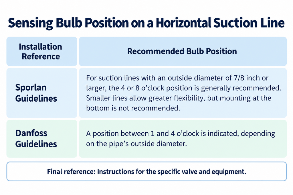
4. The Bulb’s Clock Position Depends on Pipe Diameter and Manufacturer
Clock positions describe the bulb’s location around the cross-section of a horizontal pipe: 12 o’clock is the top, and 6 o’clock is the bottom.
Therefore, 12 o’clock is not a universal requirement for all smaller pipes. Both guidelines advise against mounting at the bottom, where oil or an oil–refrigerant mixture can affect the sensed temperature.
5. Protect the Bulb from Ambient Temperature
The bulb should sense the pipe temperature, rather than the surrounding air temperature. Suitable insulation becomes particularly important where the bulb is exposed to warm airflow, radiant heat, or a significant temperature difference between the pipe and its surroundings.
Apply insulation after establishing direct contact between the bulb and pipe. No insulation layer should be placed between them. Follow the manufacturer’s guidance on whether insulation is required and which material to use. For lines operating below freezing, non-water-absorbing insulation helps prevent moisture from freezing around the bulb.
6. Vertical Pipe Mounting Is Not the First Choice
A horizontal section of the suction line is generally the preferred mounting location. If one is unavailable, an arbitrary point on a vertical pipe should not be used as a substitute.
For example, Sporlan permits installation on a vertical section with downward flow under specified conditions. Its guidelines also advise against mounting the bulb inside a trap or downstream of one, because refrigerant and oil boiling out of the trap can distort the sensed temperature.
The permitted vertical mounting location and the orientation of the bulb and capillary tube must be determined from the instructions for the specific model.
7. In Multiple-Evaporator Systems, Each Bulb Must Sense Its Own Circuit
In systems with multiple evaporators, bulb placement and piping must prevent the discharge flow from one evaporator from affecting another evaporator’s valve sensor.
Installing a bulb where flows from different circuits mix may not provide suitable temperature information for independent control of each valve.
8. Check Superheat After Installation
A visual inspection alone is insufficient to confirm correct operation. Once the system reaches suitable operating conditions, measure the pipe temperature at the bulb location and the corresponding pressure, then calculate superheat:
Superheat = Actual pipe temperature at the bulb location − Saturation temperature corresponding to the pressure at that location
If pressure is measured near the compressor, the pressure drop between the bulb and the measurement point must be accounted for. For refrigerant blends with temperature glide, use the dew-point temperature when calculating superheat.
Obtain the target superheat from the manufacturer. Before changing the valve setting, verify that the bulb is installed correctly.
In Radiran, we know Correct bulb installation means selecting a location that senses the actual evaporator outlet vapor temperature through good thermal contact, with minimal influence from the surroundings. The equipment and valve manufacturers’ instructions are the final reference for mounting location, clock position, and external equalizer arrangement.