Compressor Service Valves: How the Three Positions Work
<p>
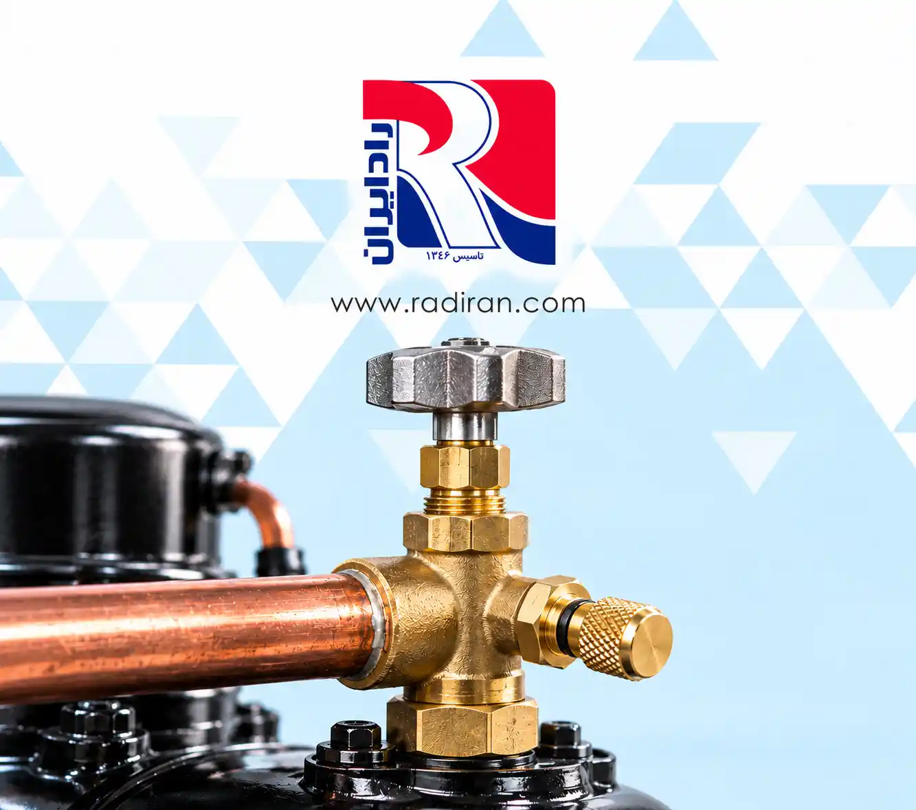
A compressor service valve provides access to a refrigeration system for pressure measurement and certain service procedures. Service valves are commonly installed at the compressor’s suction or discharge connection. Moving the valve stem changes how the compressor, refrigerant line, and gauge port communicate.
This article describes a common three-way compressor service valve. Valve designs differ, so check the instructions for the installed model before operating it.
Main parts of a service valve
A typical three-way service valve has three connections and an adjustable stem:
- Compressor connection: The common connection to the compressor.
- Refrigerant-line connection: The connection to the system’s suction or discharge line.
- Service port: The connection used for a pressure gauge or service equipment.
- Valve stem: The part that changes the internal flow paths when turned.
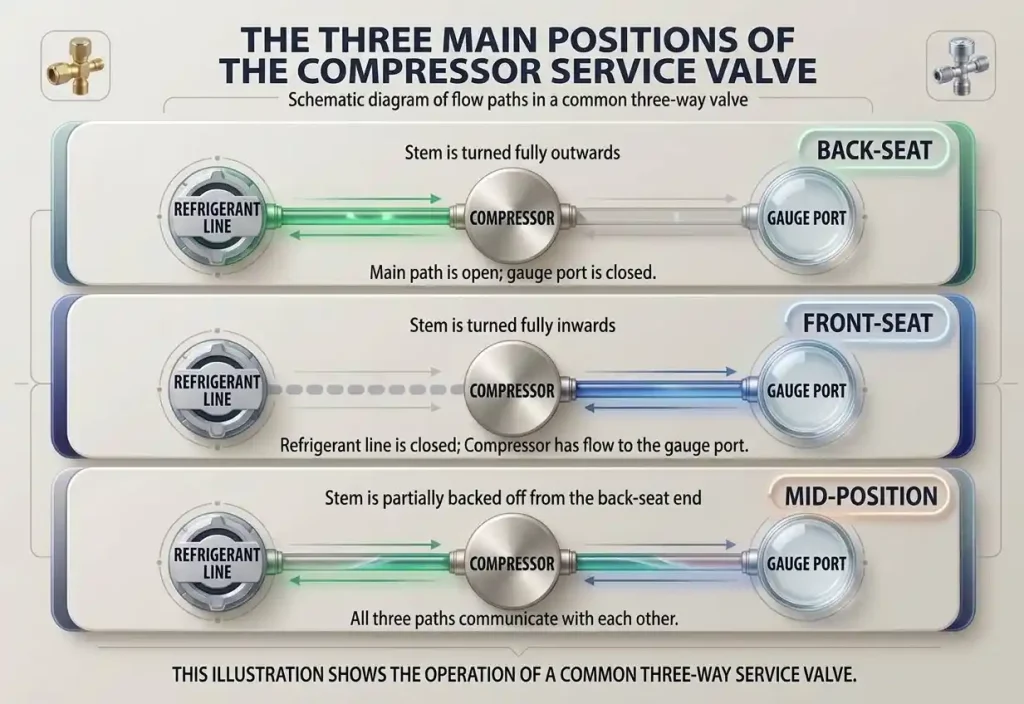
These paths apply to the three-way arrangement described above, in which the compressor connection is the common port. Other service valves may have a different configuration.
How do you read the system pressure?
When this type of valve is fully back-seated, the main refrigerant path is open but the gauge port is closed. Connecting a gauge does not, by itself, give access to system pressure.
To read pressure while keeping the main path open, Copeland’s service guidance describes turning the stem one or two turns inward from the fully back-seated position. This opens the gauge-port connection. Use this procedure only after confirming that the installed valve has the same design and operating instructions.
The service port may also be used during refrigerant charging or recovery. The procedure depends on the valve design, refrigerant, and system condition. Use appropriate recovery equipment when removing refrigerant; do not vent it directly from the service port.
Precautions when brazing a service valve
Excessive heat can damage a valve’s internal seals and components. Before brazing, check the manufacturer’s instructions for the required stem position, parts to remove, and temperature-control method. The instruction to leave the stem in a mid-position should not be applied to every valve: manufacturers specify different procedures for different designs.
Where recommended, a wet cloth can help protect the valve body from brazing heat. Keep the torch directed at the joint rather than the valve body, and check connections and seals for leaks after the work is complete. Never apply heat to a line that is under refrigerant pressure.
Stem seals and proper tools
Not every service valve has an adjustable packing nut. Even among valves that do, the operating procedure varies. One design requires its gland nut to be loosened before the stem is turned and tightened afterward. On another design, loosening the gland nut can damage an O-ring. The old instruction to always loosen the nut by a quarter turn is therefore unreliable.
Use a correctly sized wrench to avoid damaging the stem. Torque values must be taken from the instructions for the specific valve and component being tightened. If the stem does not move, identify the valve and check its sealing arrangement before applying more force. Striking the stem with a hammer is not a general troubleshooting method.
Conclusion
On a common three-way compressor service valve, the back-seated position opens the main line and closes the gauge port; the front-seated position closes the line connection and opens communication between the compressor and gauge port; and the mid-position connects all three. Always follow the installed valve’s instructions for brazing, seal adjustment, and tightening torque.
<p>