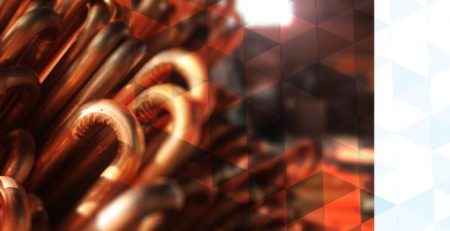
Research: Oil Cooler (Copper Fin-and-Tube Coil Heat Exchanger)
Introduction
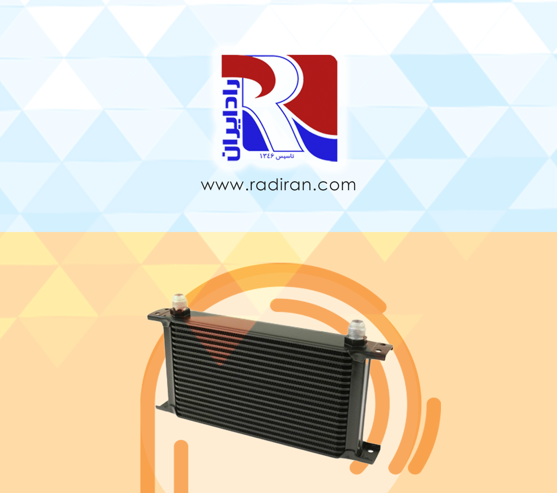
An oil cooler is a device used to reduce the temperature of oil in hydraulic systems, lubricating systems, and gearboxes. One common type is the copper fin-and-tube coil heat exchanger, which is widely used because copper has high thermal conductivity and the fins provide a large heat-transfer surface.
Construction and Components
- Shell and frame: The housing that holds the coil and connections; commonly made of steel or aluminum and designed to resist corrosion and pressure.
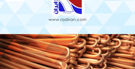
- Coil (copper tubes): Copper tubes through which oil flows (depending on the design, oil may flow inside the tubes or outside them). Copper is chosen due to its high thermal conductivity.
- Fins: Metal fins (usually aluminum or copper) attached around the tubes to increase the heat transfer surface area. Fins can be plain, louvered, wavy, or have different lengths and densities.
- Oil inlet/outlet: Threaded or flanged connections that direct oil into and out of the coil.
- Air passage or fan (for air-cooled types): To direct air through the fins; in vehicle or industrial installations a fan is often used.
Operating Principle
- The copper fin-and-tube exchanger transfers heat between two fluids (oil and air or oil and another coolant).
- Hot oil enters the copper tubes; heat conducts through the tube wall to the fins and then to the air (or to a secondary coolant).
- The rate of heat transfer depends on temperature difference, material thermal conductivity, the heat transfer surface area, and convective heat transfer coefficients.
The basic steady-state heat-transfer relation:
Q=U A ΔTlmQ=UAΔTlm
where:
- QQ: heat transfer rate (W)
- UU: overall heat transfer coefficient (W/m^2·K)
- AA: effective heat-transfer area (m^2)
- ΔTlmΔTlm: log mean temperature difference between the fluids
For finned exchangers the effect of fins should be included:
Aeff=Atube+ηf AfinAeff=Atube+ηfAfin
where ηfηf is the fin efficiency.
Technical Properties and Key Parameters
- Thermal conductivity of copper: ≈385 W/m\cdotpK≈385 W/m\cdotpK — enables fast heat conduction from oil to fins.
- Internal convective heat transfer coefficient (oil inside tube): Dependent on oil viscosity, flow velocity and oil properties; often lower than the convective coefficient of air over fins.
- Oil flow rate (Q): The volumetric or mass flow rate determines residence time and outlet temperature change.
- Pressure drop (ΔPΔP): Pressure loss through the tubes that must be acceptable for the pump and hydraulic system.
- Fin area and fin density (FPI – fins per inch): Increasing FPI raises surface area but may reduce effectiveness of each fin; optimal FPI depends on air flow and pressure drop.
- Fin efficiency (ηfηf): Depends on fin thickness, fin material conductivity, and temperature difference between fin and air.
- Corrosion resistance: Material selection and protective coatings should be considered in corrosive environments (avoid direct contact of copper with certain aggressive fluids).
- Operating temperature range: Depending on fluid and materials, typically from below freezing to several hundred °C for special applications.
- Heat capacity (C_p) of oil: Determines the amount of heat stored in the oil and rate of temperature change.
Flow Configurations and Types
- Forced-air cooling: A fan forces air through the fins; common in vehicles, generators, and electrical equipment.
- Natural convection: No fan; suitable for low heat loads and vertical installations.
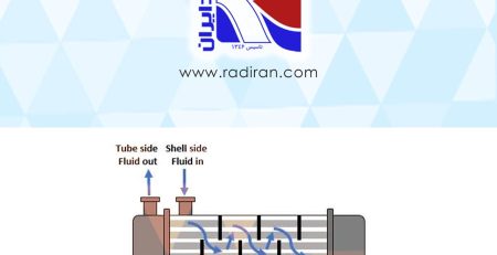
- Oil-to-water (or liquid) cooling: Copper coil inside a shell where water or another coolant flows in the shell side (used in closed-loop cooling).
- Tube arrangements: Single-pass, multi-pass, serpentine, or parallel tubes to optimize ΔT and pressure drop.
Design and Engineering Considerations
- Determine heat duty: calculate QQ based on power losses in the oil or heat input from equipment.
- Select tube and fin area and the number of tubes to achieve the desired temperature drop.
- Calculate internal pressure drop (ΔPΔP) using friction factors and the Darcy–Weisbach equation.
- Choose fin and tube materials considering heat transfer and corrosion resistance.
- Design mechanically for pressure, vibration, and thermal expansion (especially due to differing coefficients of thermal expansion between copper and the shell).
- Check mass, dimensions and installation space constraints.
- Perform hydrostatic and leak tests after fabrication.
Advantages and Disadvantages
Advantages:
- High thermal conductivity due to copper and enhanced surface area from fins.
- Compatibility with forced-air systems; performance can be increased with a fan.
- Simplicity and serviceability; tubes and fins are manufacturable and replaceable.
Disadvantages:
- Corrosion sensitivity, especially in marine or chemically aggressive environments.
- Higher pressure drop in designs with narrow tubes or complex flow paths.
- Weight and size can be larger than some alternative heat exchangers depending on design.
Applications
- Industrial hydraulic systems: cooling hydraulic oil in presses, cranes, and machine tools.
- Gearboxes and power-transmission systems: preventing gearbox oil overheating and preserving viscosity.
- Generators and diesel engines: cooling lubrication oil and gearbox oil.
- Compressors and pumps: maintaining oil temperature to protect bearings and seals.
- Marine systems: hydraulic and gearbox cooling on ships (with corrosion protection and seawater considerations).
- Power equipment and transformers: secondary heat exchangers for insulating oils in some applications.
- Food and processing industries: when using compatible oils and meeting sanitary standards.
Maintenance and Troubleshooting
- Periodically inspect for leaks and check fittings.
- Clean fins from dust and debris to prevent reduced airflow and degraded performance.
- Inspect internal surfaces for discoloration or deposits (signs of corrosion or contamination).
- Monitor pressure drop and outlet oil temperature; an increase in outlet temperature or reduced cooling indicates fouling, fan failure, or insufficient coolant flow.
- Use inlet filtration to prevent particles entering the coil and causing blockages.
Simple Numerical Example (Estimate)
Assume an oil cooling duty of Q=5 kWQ=5 kW. If the overall heat transfer coefficient U=50 W/m2⋅KU=50 W/m2⋅K and ΔTlm=20 ∘CΔTlm=20 ∘C, the required area is approximately:
A=QU ΔTlm=500050×20=5 m2A=UΔTlmQ=50×205000=5 m2
Thus, the fin-and-tube configuration should provide an effective heat-transfer area of about 5 m^2 (including fin effectiveness).
Standards and Safety Considerations
- Follow relevant pressure and material standards (for example ASME for pressure equipment in some jurisdictions).
- Safety precautions when working with hot oil and pressurized systems (burn and leak hazards).
- In marine or corrosive environments use suitable coatings or corrosion-resistant alloys.
Conclusion
A copper fin-and-tube coil oil cooler is an effective, reliable, and relatively economical solution for cooling oil in many stationary and mobile systems. Proper selection of size, materials, and configuration according to thermal duty, space constraints, and environmental conditions is critical. With correct maintenance and design, these coolers significantly extend oil life and improve system performance.
If you like, I can:
- produce a sample design with tube/fins counts and dimensions for a specified heat duty;
- compute detailed pressure-drop and select a suitable pump/fan;
- recommend corrosion-resistant materials and coatings for a given environment.

