Impact of 180° U-Bend Defects on the Performance of Fin-Tube Coils
<p>
Overview
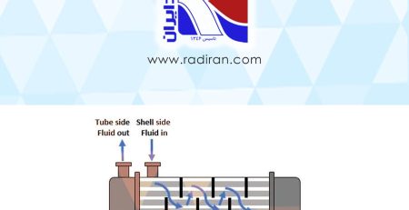
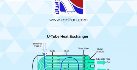
In fin-tube heat exchangers, the 180° U-bend region plays a critical role in fluid distribution, heat transfer, and pressure drop. When the bend is manufactured correctly—with proper curvature, constant internal diameter, and smooth internal surface—the flow field and thermal performance remain close to design values. However, two common manufacturing defects in the U-bend can severely degrade performance: local corrugation and local flattening. This document provides a technical assessment of all three conditions.
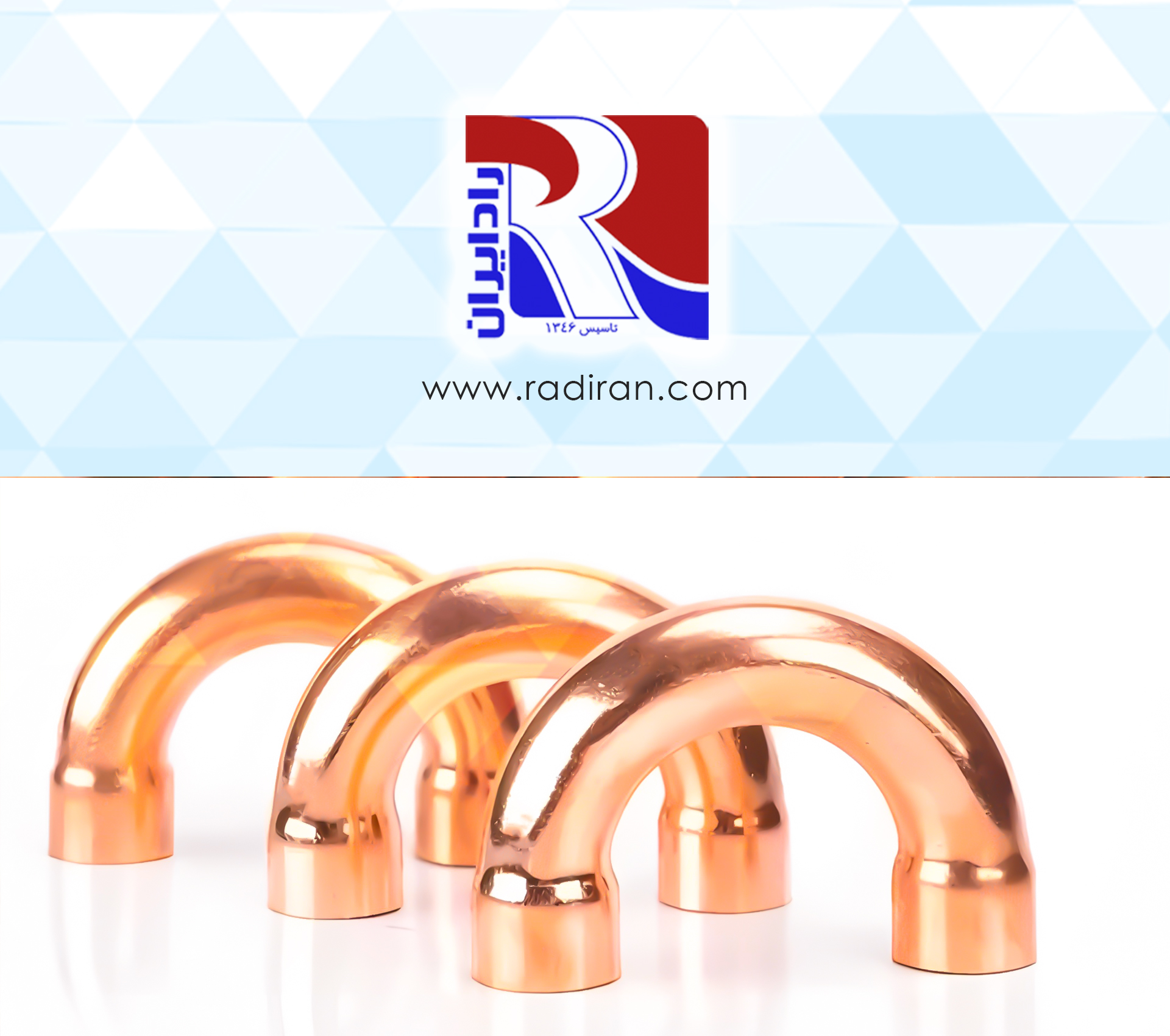
1. Standard 180° U-Bend (No Defect)
Geometry
Uniform curvature with a designed bend radius; internal surface remains smooth, and the flow passage retains its nominal diameter.
Fluid-Thermal Effects
-
Minimal flow separation or large vortex formation
-
Stable velocity and temperature distribution
-
Internal convective heat-transfer coefficient remains close to the intended design value
Pressure Drop and Pumping Requirements
-
Predictable, minimal pressure drop
-
Pumping power remains within the design envelope
Structural Integrity and Fin Contact
-
Proper tube-to-fin mechanical contact was preserved
-
Fatigue life of the bend remains within expected limits
2. Local Corrugation in the U-Bend
Geometry
Localized wrinkling on the inner or outer radius of the bend, creating non-uniform cross-sectional deformation and internal surface roughness.
Fluid-Thermal Effects
-
Local turbulence intensification and unstable boundary layers
-
Enhanced local mixing that may increase heat transfer in a limited region
-
Flow non-uniformity across the coil
Pressure Drop and Pumping Requirements
-
Significant increase in pressure drop due to added resistance
-
Higher pumping power and operating cost
Operational Drawbacks
-
Higher susceptibility to fouling and blockage at corrugated zones
-
More difficult inspection and cleaning
-
Stress concentrations at corrugated points, increasing risk of fatigue crack initiation
3. Local Flattening in the U-Bend
Geometry
Reduction in tube diameter with ovalization or flattening of the cross-section, decreasing flow area and altering the wetted perimeter.
Fluid-Thermal Effects
-
Increased local flow velocity within the constricted section
-
Possible localized enhancement of convection
-
Distorted flow field with undesirable separation and vortex formation
-
Potential deterioration of downstream temperature uniformity
Pressure Drop and Pumping Requirements
-
Elevated pressure drop due to reduced area and turbulence
-
Possible increase in back-pressure on the upstream circuit
Structural and Functional Issues
-
Compromised tube-to-fin thermal contact due to geometric distortion
-
Local wall thinning and stress concentration
-
Increased likelihood of localized corrosion and leakage
Engineering Summary
-
-
The standard 180° bend is the optimal configuration, providing predictable hydraulic and thermal performance with maximum structural reliability.
-
Both corrugation and flattening are detrimental manufacturing defects.
Although each may create small regions of enhanced heat transfer, these limited benefits are overshadowed by:-
Elevated pressure drop
-
Higher pumping energy
-
Increased fouling tendency
-
Reduced mechanical durability
-
Higher corrosion and leakage risk
-
-
Engineering Recommendation
Prevent these defects through:
-
Controlled bending processes (mandrel-supported bending, proper radius selection, adequate lubrication)
-
Visual and NDT inspection focused on U-bend zones
-
Local CFD evaluation when defects are detected
-
Repairing or replacing defective coil sections to ensure long-term system performance
<p>