Flow of Refrigerant and Water in a Shell-and-Tube Evaporator in a Vapor-Compression Chiller
A shell-and-tube evaporator is one of the most common heat exchanger types used in vapor-compression chillers. This article examines the refrigerant and water flows, their thermal and hydrodynamic interactions, and design and operational considerations from a mechanical engineer’s perspective.
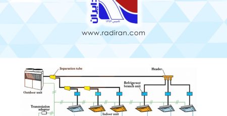
General Description and Flow Configuration
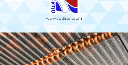
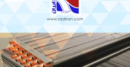
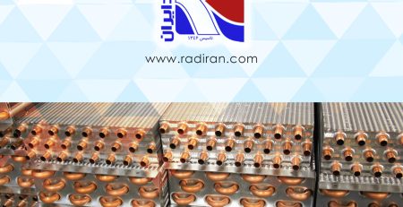
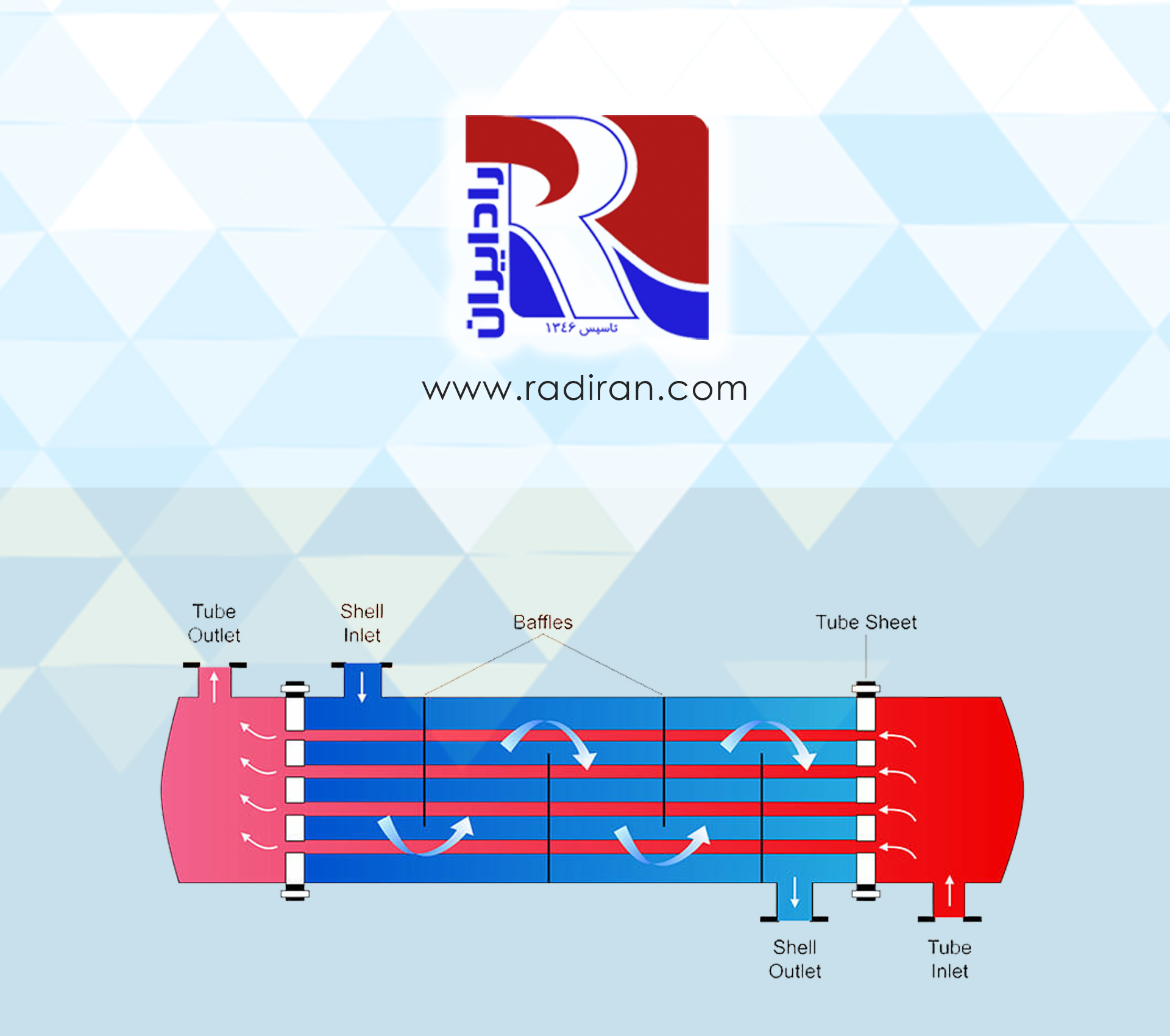
A shell-and-tube evaporator typically consists of a bundle of tubes placed inside a shell. In a typical chiller, the refrigerant flows inside the tubes while the chilled water (or brine) flows in the shell; depending on design, this arrangement can be reversed. In many HVAC applications water is routed in the shell to facilitate maintenance and access to the tube bundle.
Refrigerant Flow: Phase Change and Heat Transfer
The refrigerant entering the evaporator commonly arrives as a subcooled or saturated liquid and gradually evaporates along the tubes. This process includes three thermal regions:
• Liquid heating (possibly short): raising the liquid refrigerant temperature up to the saturation temperature.
• Phase-change evaporation (dominant): liquid-to-vapor conversion at approximately constant saturation temperature; this region involves large latent heat absorption.
• Vapor superheating (if it occurs): increasing the vapor temperature after evaporation is complete; in chillers this region is typically minimized to ensure dry vapor enters the compressor.
The refrigerant flow configuration (single-pass, multi-pass, U-tubes, or distribution manifolds) directly affects the internal heat transfer coefficient and pressure drop. Two-phase flow inside tubes introduces hydrodynamic and heat transfer complexities that require empirical correlations; heat transfer coefficients depend on Reynolds number, vapor quality, and geometry.
Water Flow: Distribution and External Heat Transfer Coefficient
The chilled water in the shell flows around the tubes and removes heat. Important water flow aspects include:
• Flow regime: laminar or turbulent, determined by the Reynolds number; turbulent flow provides much higher heat transfer coefficients.
• Overall heat transfer coefficient: the combination of internal (refrigerant-side), tube wall conduction, and external (water-side) resistances determines the overall U.
• Pressure drop and velocity distribution: baffles in the shell are used to direct flow and increase heat transfer at the expense of higher pressure drop.
Interactions and Design Considerations
• Corrosion and fouling control: water quality and chemical treatment are critical to prevent fouling on tube surfaces; fouling significantly reduces heat transfer.
• Refrigerant pressure drop effects: pressure drop of refrigerant in tubes can locally reduce evaporation temperature and change vapor quality; design must optimize allowable pressure loss.
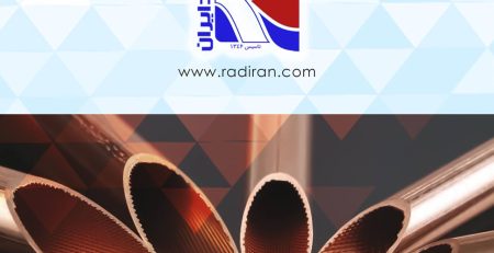
• Tube geometry and material: tube diameter, wall thickness, pitch, and material (commonly copper or stainless steel) influence performance.
• Compressor protection: ensuring dry vapor enters the compressor (avoiding liquid carryover) requires level controls and appropriate superheat margin.
• Energy efficiency and seasonal performance: flow strategy, heat transfer surface area, and low-loss hydraulic design can improve the chiller’s COP.
Conclusion
In a shell-and-tube evaporator of a vapor-compression chiller, the two-phase refrigerant flow inside the tubes and the water flow in the shell interact in a complex way that determines the overall heat transfer coefficient and system performance. Successful design requires balancing increased heat transfer (for example, via baffles and promoting turbulence), minimized pressure drop, fouling and corrosion management, and compressor protection. Using empirical two-phase flow correlations and hydrodynamic analysis allows development of a design that delivers both high thermal efficiency and reliable operation.