Screw Compressor: Working Principles and Operation
Introduction to Screw Compressors
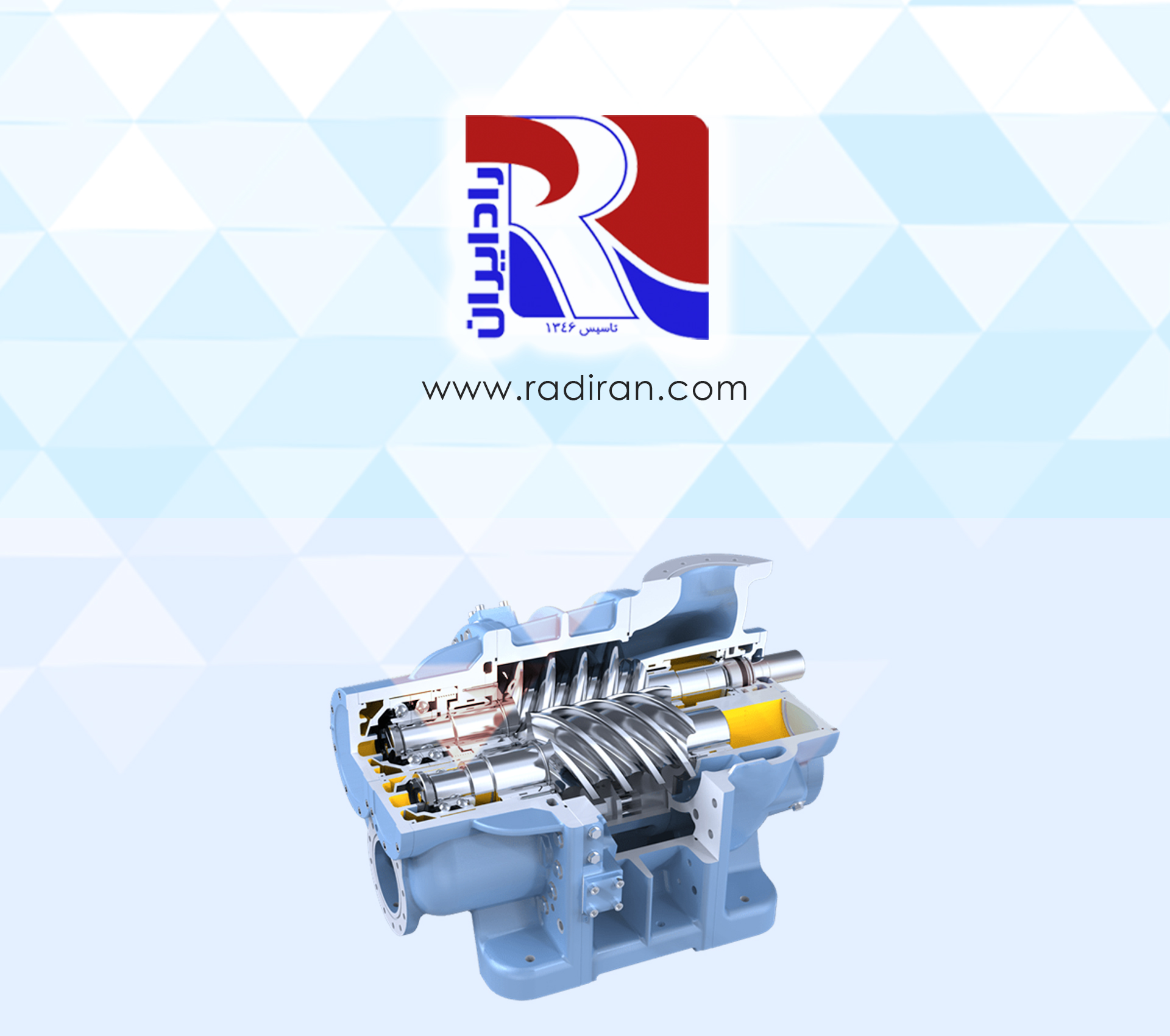
A screw compressor is a type of rotary compressor made up of two helical rotors: a male rotor and a female rotor. These rotors are designed to rotate around each other and compress gas. One of the rotors is connected to the main motor, while the other rotors move due to the first rotor’s rotation. This process reduces the volume of gas in the rotor’s grooves, resulting in compression.
Structure and Design of the Rotors
The screw compressor consists of male and female rotors. The male rotor has convex lobes, while the female rotor features concave cavities. This design allows gas (air) to be trapped between them when the rotors spin in harmony. The male rotor rotates at a higher speed than the female rotor, making the latter move effectively.
Stages of Operation of the Screw Compressor
Screw compressor operation occurs in four main stages, as outlined below:
1. Suction Stage: In this stage, an opening valve allows refrigerant gas to enter the compressor chamber.
2. Initial Compression Stage: When the compressor is activated, both the male and female rotors begin to rotate, and the space between their teeth decreases rapidly due to their swift rotation.
3. Gas Transfer Stage: During this phase, the refrigerant gas is trapped in the gaps between the rotors and moves downward in the chamber. Compression continues until the rotors near the discharge opening of the compressor, resulting in very high pressure at this stage.
4. Discharge Stage: The pressure generated causes the discharge valve of the compressor to open, allowing the compressed refrigerant to exit through the discharge point.
Conclusion
Screw compressors, with their unique design and high efficiency in compressing air, are widely used in various industries, including HVAC and industrial equipment. The regular and continuous operation of these devices is crucial, enabling users to achieve high efficiency in their applications.

